The Mechanical Typist
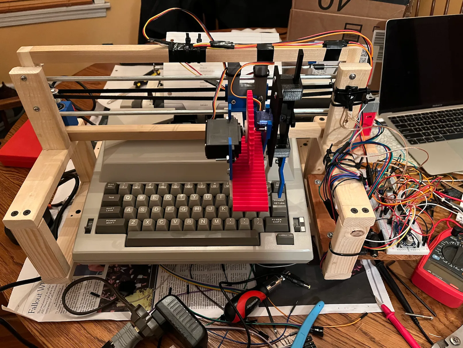
For my final project I wanted to try something that posed enough of a novel challenge, while still incorporating elements of my previous creations. Unfortunately, I ended up setting the bar a little too high, and my major goals were impossible to complete within the time frame. Luckily, what I did end up with is still pretty cool, and really only a few steps away from my original plan. The final result is what I’ve decided to call the Mechanical Typist, more specifically, a robot that slides over a keyboard and can tap away at the keys to spell out messages, much like a human. For my design I didn’t use just any keyboard, but rather a full typewriter, for an extra retro feel. This project was pretty directly inspired by the previous one, a drawing robot, which got me thinking about robots doing tasks usually performed by humans in a somewhat roundabout way.
Construction
A whole lot of parts went into making this project, since it was developed incrementally over time, and had some pretty complex requirements. While I was planning things out, I had to take special care to make the most efficient use of the tools and resources available to me. This lead to me building an entirely wooden frame structure to fit around the typewriter while I was at home and had access to the right tools. The fact that it was made out of wood meant that as I transitioned into designing the mechanical parts, which were mostly 3d printed, holes could be drilled and then things could be screwed on, piece by piece. This strategy was, for the most part, pretty successful, and gave me the flexibility and margin for error that I was looking for. As far as the 3d printed parts, I also tried to add as much flexibility as possible there too. Almost all of them are either designed to be screwed together, or bolted, which made it easy to replace parts and adjust them as I went.
The Axes
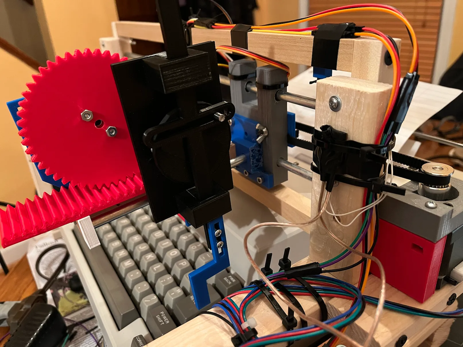
Since I decided to build the robot in the gantry style for the greatest degree of precision, and simplicity of control, it had to have three separate axes in order to produce the required range of movement. Each axis uses a different mechanism to convert rotational to linear motion, depending on the given precision and space requirements. I decided to make the main x-axis belt-driven and controlled by a stepper motor, much like a 3d printer. There are two pulleys on either side of the machine, and then a block that slides on a set of rails, pulled by the belt. Attached to the block is the y-axis (or depth control) which I decided to use a rack and pinion mechanism for, since this allowed me to use a servo motor instead of a stepper. This is important because steppers have no positional feedback, so you need some kind of homing system in place in order for them to work accurately. With my design, only the x-axis needs a limit switch for homing. With one half-rotation of the servo, the arm is extended to its full length, and can then be retracted by rotating back half-way. I applied a similar configuration to the z-axis, or the finger that actually presses the keys. Instead, of a rack and pinion, another simple mechanism called a scotch yoke is used, and one half-rotation fully extends the “finger” to press a key.
Circuit
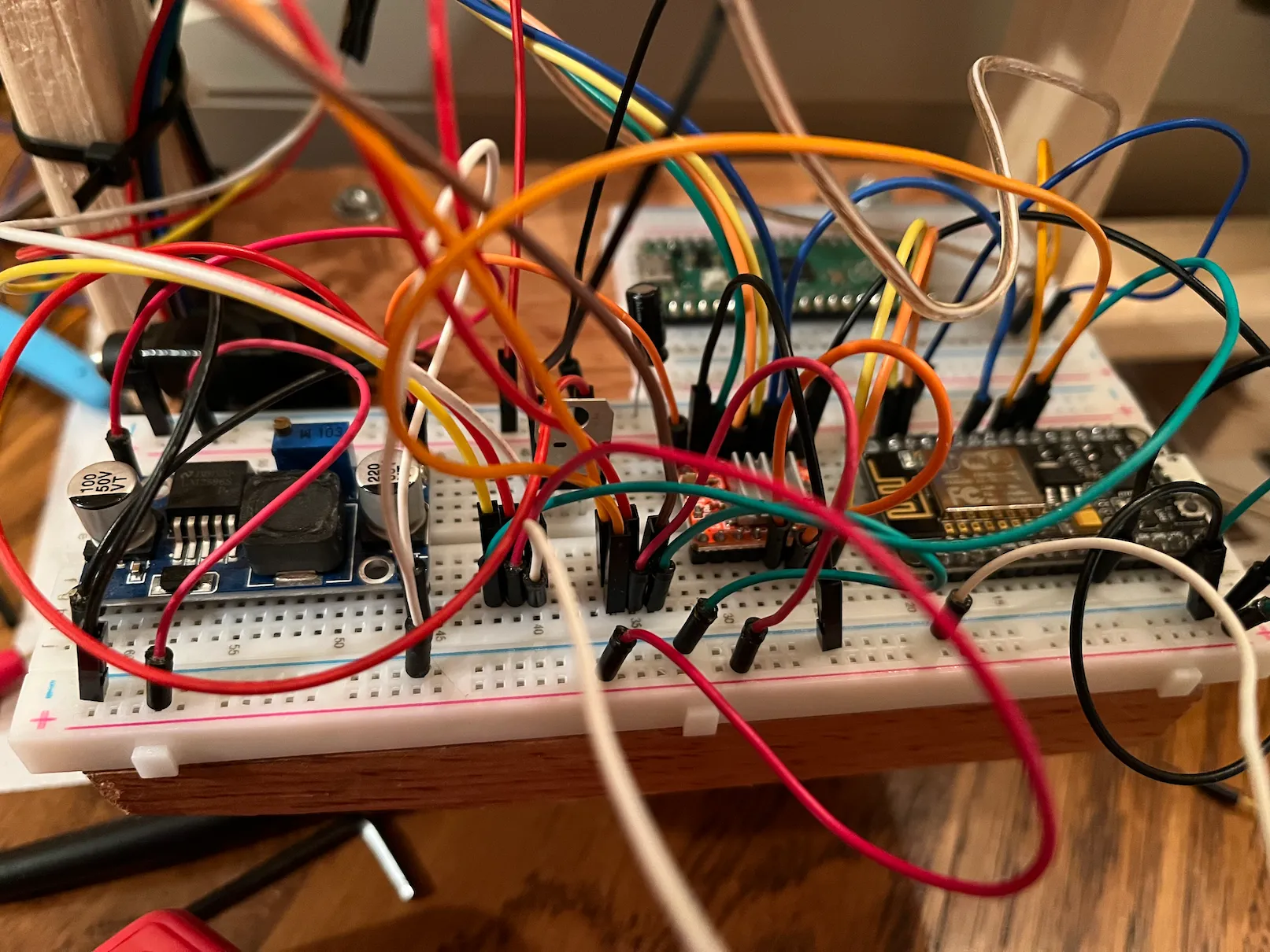
The power supply for this project has a kind of waterfall setup, where a buck converter steps down the 12 volts from the wall plug to 9 volts, which in turn is reduced to 5 volts by a linear regulator. The 9 volt power is only used by the stepper, and then the servos and the esp8266 I’m using to control everything get fed the 5 volts. Aside from that, there’s also a stepper driver being used that makes it much easier to control.
Software
Right now, the program to make the typewriter do whatever it should do is loaded onto the esp8266 directly. The plan for the future is to have the esp8266 act as a kind of ancillary chip that can communicate with another board through I2C. It would get sent simple commands, telling it things like “home the stepper motor”, or “go to location x” produced by some other program on the main board. This kind of abstraction would make it pretty easy to connect to other devices and add functionality. As far as the existing software, it’s not too complicated. It does some math to convert rotation of the motors to an actual traveled distance, allowing it to go to a specific point. Right now, it’s only able to play through a set of keyframes of hardcoded points. This still allows it to do some cool things, though, like type out a full message, as long as it has been configured beforehand.
Difficulties
Clearly, as I wasn’t able to fully complete my original goal, there were some setbacks along the way. The main problem was the unavoidable one of it being to much complexity to handle in the given time frame, but I also ran into some annoying technical hurdles as I was building it. The biggest of these was the fact that the 3d printers on campus, I suppose succumbing to the wear and tear of finals week, were largely broken. As this project relied on a large number of 3d printed parts, parts that couldn’t be easily manufactured any other way, this turned into a significant setback. Other than that, there’s certainly a little room for improvement in the gantry mechanism, since because of slack in many places, it’s not as accurate as it easily could be with some tweaking.
Eventual Vision
The full idea, as it was conceived in the beginning, is to turn this into a poetry robot. Once it’s reliably able to act as a sort of printer for messages of arbitrary length, you could theoretically hook it up to anything. One of the coolest uses I can see would be to connect it to one of the large language text models popular now as a sort of mechanical interface. Much like the drawing robot, it could take input through speech recognition as a kind of prompt from which to craft its response. One of the areas that models such as OpenAI’s GPT-3 excel at is writing poetry, so the plan was to make a kind of Shakespeare bot that you could give a theme/title to, and it would type you out a poem in perfect meter.